I recently found time watch Blade Runner 2049, and decided to create my own version of the famed 'Blade Runner Blocks.'
History of the 'Blade Runner' Blocks
The interior shots in Blade Runner where filmed in the Frank Lloyd Wright designed Ennis House. The house, which is broadly based on Mayan themes, is one of Frank Lloyd Wright's Textile Block houses. Like the other Textile Block houses, Ennis house is constructed from thousands of precast interlocking concrete blocks, each with a patterned unique to the project.
Ennis House has been used as filming location countless times, but is most recognized for the original Blade Runner. Its unique precast textile blocks are a visible throughout the films interiors scenes. The Neo-Mayan design of the blocks mixed with the film's moody lighting firmly establishes the films interiors in unsettlingly alien future.
Designing My Own Block Mold
Detailed drawings of the Ennis House Blocks are available, but I decided to start from a pre-existing 3D model. Thingiverse User Keenan has created a 3D model of one of the texture block faces. He has made it available for download and modification under the Creative Commons License, so I can download it for my own modification and use.

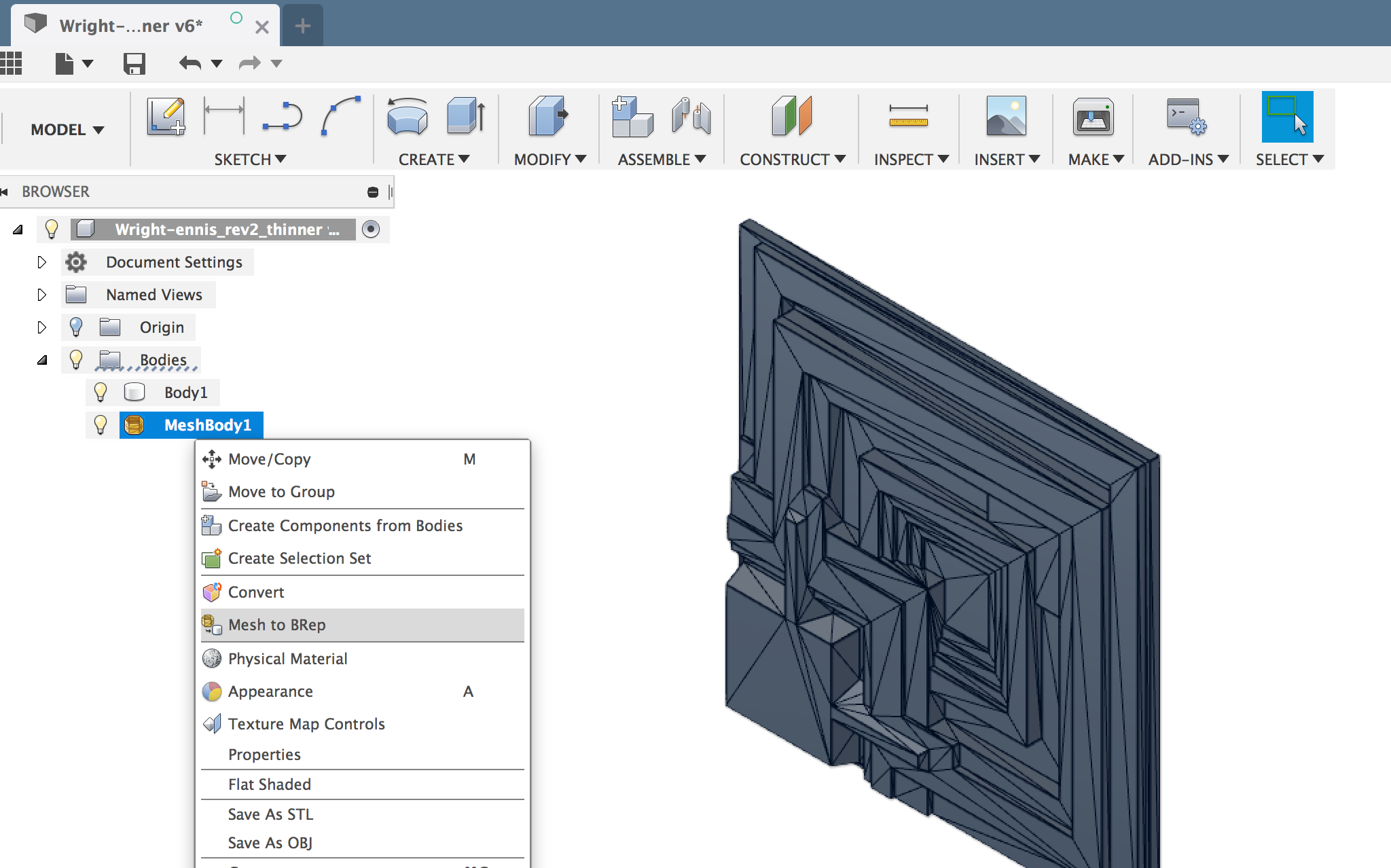
With the Keenan's original SketchUp file imported into Fusion 360, I converted it from a Mesh into a BRep. This make the 3D model much easier to edit. To do this successfully, you'll need to be in the 'Model' workspace with design history disabled. (It should already be disable when you opened the imported SketchUp File) Left click the MeshBody in the Navigator menu and select the 'Mesh to B-REP' tool.
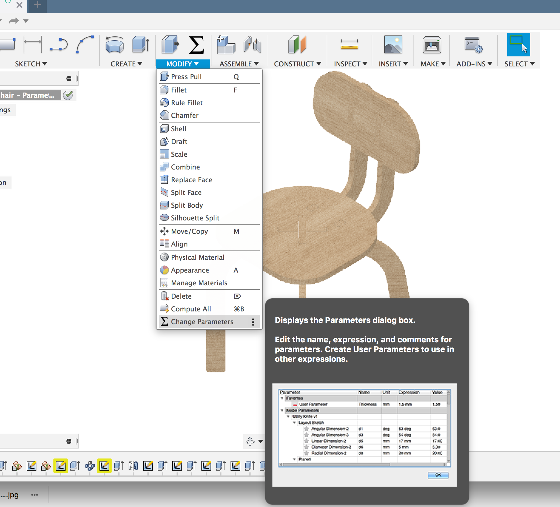
Once you have your BRep, remember to re-enable 'Capture Design History' by left clicking the root of the file's navigator tree and selecting 'Capture Design History'

To make a mold for the concrete block, I needed to inverse the surface of the block into the wall of the mold. Easy to do using Fusion's 'Combine' Tool.

The Mold will make a cube, with every side textured. So with each of the six sides being identical, I only need to draw one side! Computers are great for being lazy!
CNC Tool Pathing
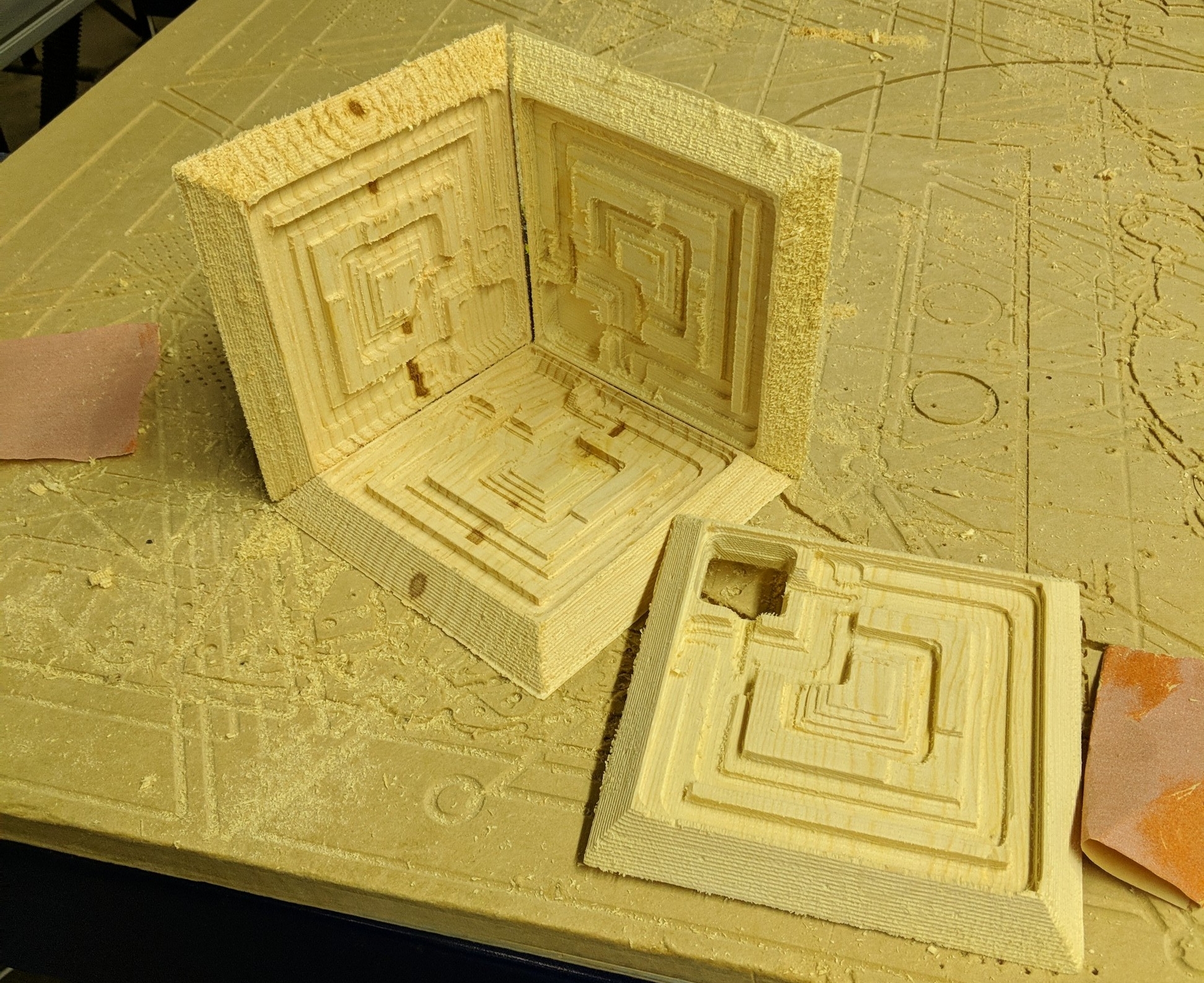
The Tool Path for this file is straightforward. First we'll mill all of the horizontal faces with a 3mm flat endmill, then we mill the walls and mold edges with a 3mm ball endmill.
I used Fusion 360's CAM Pattern tool to duplicate the G-Code 6 times in the machine's Y axis, so all 6 mold faces can be milled at once from a single 18mm thick pine board.

Be sure to check the 'order by tool' option box, so the machine will run all of the operations on all of the tiles that use the same bit before stopping for a tool change.
CNC Cutting time for all six mold faces was approximately 2 hours.
Finishing the Mold
Straight out of the CNC Machine, the pine molds are going to need some smoothing before we can cast them in concrete.
I could spend hours painstakingly sanding them, but this is intended as one time use mold so I don't want to invest that much time in it.
So after a quick sanding to remove the big stuff, I resorted to and old method to get rid of the small fibrous left overs... FIRE!

The blow touch flame burns away the rough areas, and leave a smoother surface behind. Just be sure to have a spray bottle of water handy to stop the flames if the get out of control!

Casting
I mixed the concrete fairly wet, so it would flow easily into the mold. There is no way around the how messy this process is.

I used a Hammer to bang on the sides of the mold after poring, to drive the air bubbles out and make the final block uniform in color and texture.

Opening the Mold!

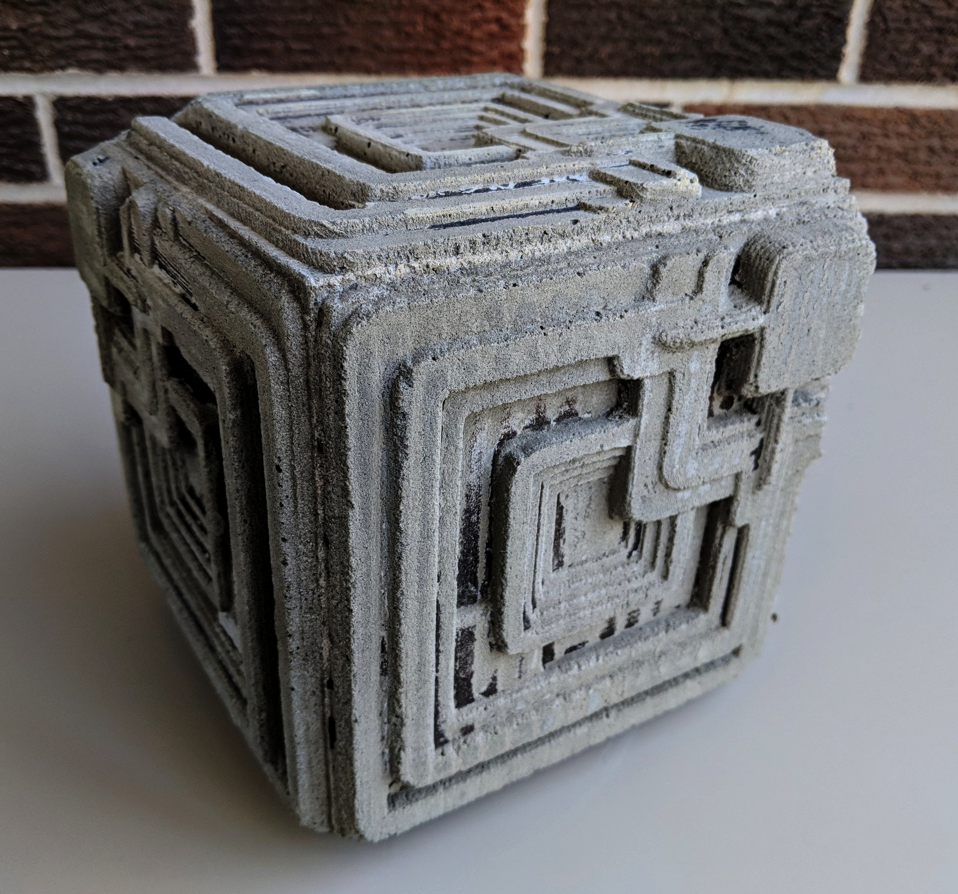
After Curing overnight, It was time to see our final Blade Runner Block. Opening this mold required a hammer, chisel, and crowbar. After 24 hour in contact with wet concrete, the soft Pine had become wet and soggy, there was no saving it.

Now that is awesome! The charred surface of the pine stuck to the concrete in a few places, and there are a few minor bubbles, but overall its an excellent result for a one day project. The rough texture of the concrete came through in a few places, just adding to the block's appearance as an aged relic.
Final Notes
Where I doing this project a second time, there are a few thing I would change. Most are related to the casting process.
- I would use 'Topping Mix' instead of the Portland Cement I used in this cast. Topping mix will more easily fill the mold and is intended to be mixed wetter without degrading.
- I would pre-coat the inside of the mold with a combination of water and a surfactant like 'Jet Dry' before pouring the concrete. The surfactant would help element some of the smaller air bubbles.
- I would redesign the mold with an internal cavity on one side instead of making it a sold cube. That way it could be used as a flower pot... At this point the only use I can find for this 8kg block of concrete is as a really awesome doorstop!
Thanks for reading! I hope you are making something awesome!
-Michael